Structural AnalysisSiemens NXNX NastranFEAStress & Deformation AnalysisMeshing
Axle — Structural & FEA Evaluation
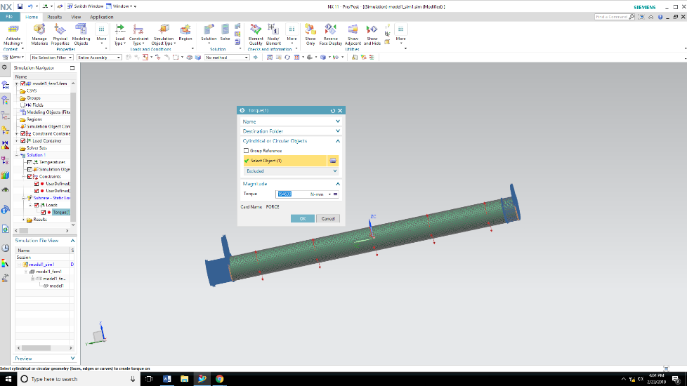
Evaluate the structural performance of an axle under representative loading conditions using Siemens NX and NX Nastran.
An axle needs to be assessed for how it deforms and where stress concentrates under load, so that the design can be confirmed safe before it is committed to service.
I built the axle model in NX, applied realistic boundary conditions and loads, meshed the geometry, and ran a finite element analysis to study deformation and stress distribution across the part.
Solid CAD model of the axle created in Siemens NX, detailed to the level needed for accurate meshing and load application.
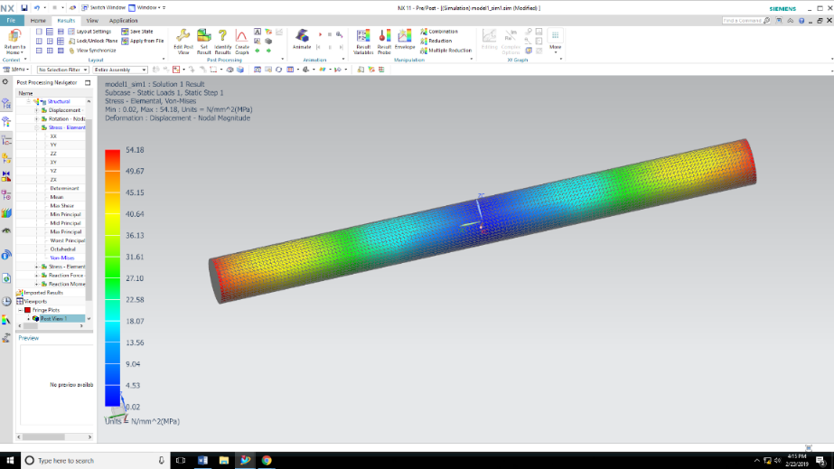
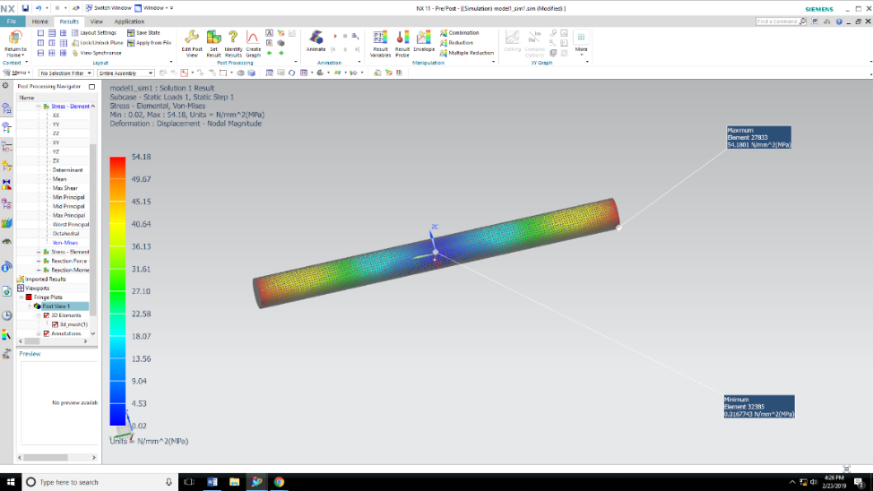
Linear static FEA solved in NX Nastran, capturing deformation and von Mises stress under the applied loading and support conditions.
Defined and checked the applied load cases and support reactions before solving, to ensure the boundary conditions represented realistic in-service behavior.
Refined the mesh density around fillets and load-application regions to capture stress gradients accurately without making the model unnecessarily heavy to solve.
Modeled as a machined shaft component, consistent with typical axle production methods.
Structural steel, evaluated using standard mechanical properties appropriate for a machined axle.
The FEA identified the regions of maximum deformation and peak stress under the applied load, giving a clear picture of the axle's structural behavior and margin.
Getting the boundary conditions and load application realistic enough that the FEA results could be trusted — resolved through careful mesh refinement and load-case review.
Mapped deformation and stress distribution across the full axle geometry.
Identified the location and magnitude of maximum deformation under the applied load.
Confirmed the axle's structural behavior against the intended loading condition.
This project reinforced my meshing and boundary-condition discipline — how much the accuracy of a stress result depends on getting the load application and support conditions right before trusting the output.