CAD PracticeSolidWorksPart DesignAssembly ModelingRendering
Quadcopter
Improve part modeling and assembly design skills in SolidWorks through a multirotor UAV exercise.
A quadcopter assembly involves multiple interacting components that need correct positioning and clearance to look and function convincingly.
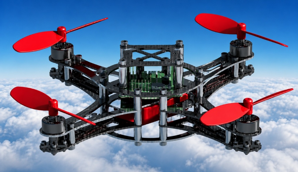
I modeled the frame, propellers, motors, and supporting structure, then assembled them into a complete model with proper component positioning before rendering the result.
Complete quadcopter assembly in SolidWorks, including frame, motor mounts, and propellers.
Kept motor and propeller placement symmetric and consistent with real multirotor geometry for visual and mechanical plausibility.
Positioning multiple interacting components (motors, propellers, frame) with correct clearances so the assembly reads as mechanically plausible.
Completed a fully assembled, rendered quadcopter model.
Reinforced assembly-modeling discipline — mating parts correctly so a multi-component design reads as one coherent product.